Discover how to take into account tooling deformations with ease when designing with CATIA.
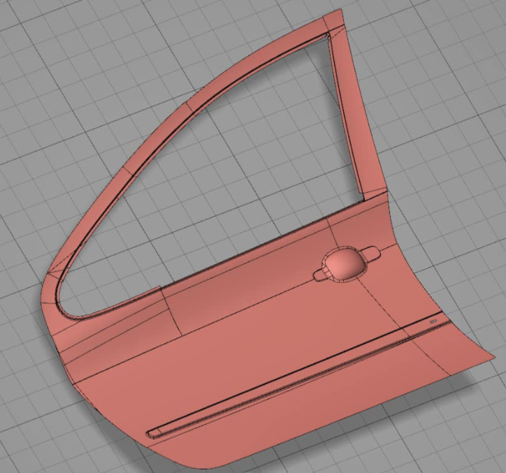
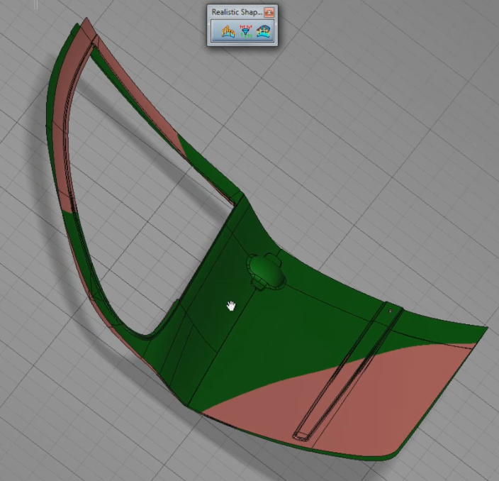
The designer’s CAD model generally illustrates the desired production result. However, the manufacturing process may generate deformations, such as springback of sheet metal or shrink marks on injection-molded plastic parts. To obtain the desired shape at the end of the process, it is therefore necessary to adapt the toolpath or the CAD model of the mold in order to take into account such deformations.
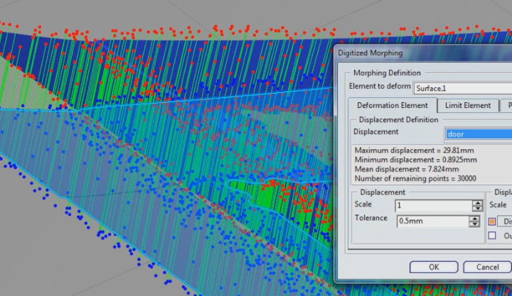
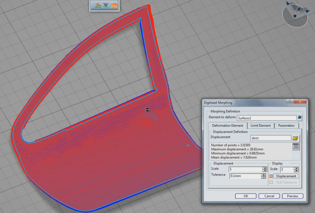
Scans of manufactured parts deformed by the manufacturing process make it possible to quantify deviations from the ideal model, similarly to the way in which finite element analysis, such as that performed by Abaqus, makes it possible to predict the impact of the manufacturing process. By combining the results of one of these analyses with CATIA’s Reverse Shape Optimizer module, correcting the CAD model becomes quick and easy, making it possible to eliminate the need for costly finishing work.
This video demonstrates how to correct the CAD model using results provided by Abaqus in less than 3 minutes.
Make life easier with CATIA.

